醬是創客的ESP32教學主題第20篇,以NodeMCU-32S(使用Arduino IDE)來實作教學,本篇教學Arduino透過SPI介面傳送/接收CAN bus通訊協議,來傳送接收Standard/Extended/Remote request Frame
以下是我們今天的目標
- 傳送接收Standard/Extended/Remote request Frame
- 了解CAN bus ID/DLC/DATA的關聯
設備:
安信可原廠/副廠NodeMCU-32S #露天拍賣 #蝦皮購物
醬是創客CAN bus模組 #露天拍賣 #蝦皮購物
CAN bus發送端接線方式:
NodeMCU-32S(GPIO5)–SPI訊號–醬是創客CAN bus模組(CS)
NodeMCU-32S(GPIO18)–SPI訊號–醬是創客CAN bus模組(SCK)
NodeMCU-32S(GPIO19)–SPI訊號–醬是創客CAN bus模組(SO)
NodeMCU-32S(GPIO23)–SPI訊號–醬是創客CAN bus模組(SI)
DC 5V(+)–醬是創客CAN bus模組(VCC)
DC 0V(-)–醬是創客CAN bus模組(GND)
發送端醬是創客CAN bus模組(H)-CAN訊號–接收端醬是創客CAN bus模組(H)
發送端醬是創客CAN bus模組(L)-CAN訊號–接收端醬是創客CAN bus模組(L)
CAN bus接收端接線方式:
NodeMCU-32S(GPIO5)–SPI訊號–醬是創客CAN bus模組(CS)
NodeMCU-32S(GPIO18)–SPI訊號–醬是創客CAN bus模組(SCK)
NodeMCU-32S(GPIO19)–SPI訊號–醬是創客CAN bus模組(SO)
NodeMCU-32S(GPIO21)–DI訊號–醬是創客CAN bus模組(INT)
NodeMCU-32S(GPIO23)–SPI訊號–醬是創客CAN bus模組(SI)
DC 5V(+)–醬是創客CAN bus模組(VCC)
DC 0V(-)–醬是創客CAN bus模組(GND)
發送端醬是創客CAN bus模組(H)-CAN訊號–接收端醬是創客CAN bus模組(H)
發送端醬是創客CAN bus模組(L)-CAN訊號–接收端醬是創客CAN bus模組(L)
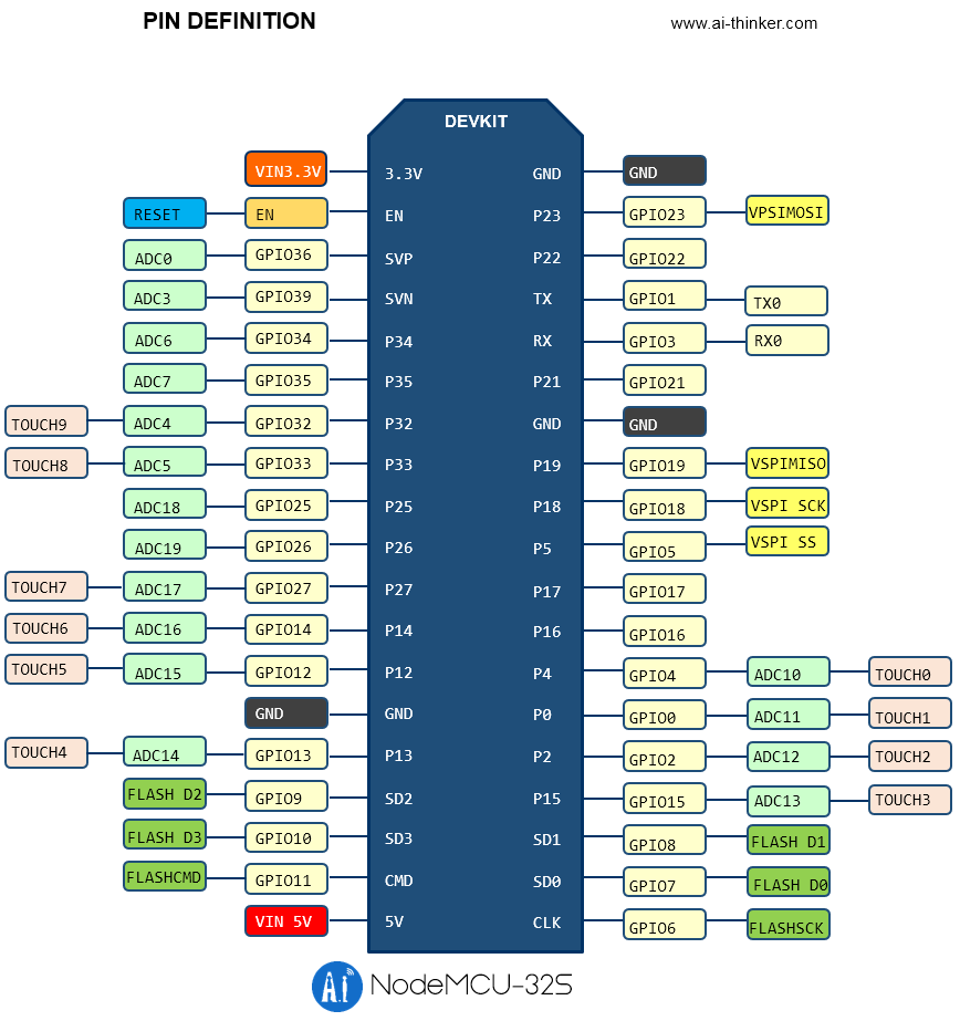
Ai-Thinker安信可NodeMCU-32S的腳位圍(資料來源:安信可)
醬是創客CAN bus模組相關資料
CAN bus的速率是依靠晶片與振盪器而定,以MCP2515這顆晶片來說它理論可以達到1Mbps,這個前提是配合16MHz或20MHz振盪器,如果需要跑到1Mbps需求者,需自行將振盪器元件轉焊換成16MHz或20MHz,一般來說這個模組使用8MHz振盪器,速度會選用125Kbps,以我們做過的專案來說125Kbps其實就很夠用
Arduino IDE mcp2515.h 安裝說明:
1. 下載此ZIP檔案https://github.com/autowp/arduino-mcp2515/archive/master.zip
2. 打開Arduino IDE >> 草稿碼 >> 匯入程式庫 >> 加入.ZIP程式庫,並選擇剛剛下載的ZIP檔案
3. 安裝好後,關閉Arduino IDE,並再重新啟動Arduino IDE
Arduino CAN bus發送端範例程式碼如下,請注意程式碼中的 & 需自行轉換成&符號
//醬是創客 開發實作的好夥伴
#include "WiFi.h"
#include <SPI.h>
#include <mcp2515.h>
struct can_frame canMsg1;
struct can_frame canMsg2;
//定義使用GPIO5當SPI的CS
MCP2515 mcp2515(5);
void setup() {
//standard frame
canMsg1.can_id = 0x0F6;
canMsg1.can_dlc = 8;
canMsg1.data[0] = 0x8E;
canMsg1.data[1] = 0x87;
canMsg1.data[2] = 0x32;
canMsg1.data[3] = 0xFA;
canMsg1.data[4] = 0x26;
canMsg1.data[5] = 0x8E;
canMsg1.data[6] = 0xBE;
canMsg1.data[7] = 0x86;
//extended frame
canMsg2.can_id = 0x12345678 | CAN_EFF_FLAG;
canMsg2.can_dlc = 8;
canMsg2.data[0] = 0x0E;
canMsg2.data[1] = 0x00;
canMsg2.data[2] = 0x00;
canMsg2.data[3] = 0x08;
canMsg2.data[4] = 0x01;
canMsg2.data[5] = 0x00;
canMsg2.data[6] = 0x00;
canMsg2.data[7] = 0xA0;
Serial.begin(115200);
mcp2515.reset();
//使用8MHz振盪器並搭配125Kbps速度
mcp2515.setBitrate(CAN_125KBPS, MCP_8MHZ);
//使用CAN bus NormalMode
mcp2515.setNormalMode();
Serial.println("Chosemaker: Write to CAN");
}
void loop() {
//送出standard frame
mcp2515.sendMessage(&canMsg1);
delay(1000);
//送出extended frame
mcp2515.sendMessage(MCP2515::TXB1,&canMsg2);
delay(1000);
}
Arduino CAN bus接收端範例程式碼如下,請注意程式碼中的 & 需自行轉換成&符號
//醬是創客 開發實作的好夥伴
#include "WiFi.h"
#include <SPI.h>
#include <mcp2515.h>
struct can_frame canMsg;
//定義CAN_INT使用GPIO21
#define CAN_INT 21
//定義使用GPIO5當SPI的CS
MCP2515 mcp2515(5);
char msgString[128];
void setup() {
Serial.begin(115200);
mcp2515.reset();
//使用8MHz振盪器並搭配125Kbps速度
mcp2515.setBitrate(CAN_125KBPS, MCP_8MHZ);
//使用CAN bus NormalMode
mcp2515.setNormalMode();
//CAN_INT為INPUT模式
pinMode(CAN_INT, INPUT);
Serial.println("------- CAN Read ----------");
Serial.println("ID DLC DATA");
}
void loop() {
//CAN_INT低電位時開始收資料
if(!digitalRead(CAN_INT))
{
//讀取CAN Frame資料
mcp2515.readMessage(&canMsg);
//判斷ID是standard (11 bits) frame還是extended (29 bits)frame
if((canMsg.can_id & 0x80000000) == 0x80000000)
sprintf(msgString, "Extended ID: 0x%.8lX DLC: %1d Data:", (canMsg.can_id & 0x1FFFFFFF), canMsg.can_dlc);
else
sprintf(msgString, "Standard ID: 0x%.3lX DLC: %1d Data:", canMsg.can_id, canMsg.can_dlc);
Serial.print(msgString);
//判斷ID是否為remote request frame
if((canMsg.can_id & 0x40000000) == 0x40000000){
sprintf(msgString, " REMOTE REQUEST FRAME");
Serial.print(msgString);
} else {
//取出frame資料
for(byte i = 0; i<canMsg.can_dlc; i++){
sprintf(msgString, " 0x%.2X", canMsg.data[i]);
Serial.print(msgString);
}
}
Serial.println();
}
}
我們在發送端每隔一秒鐘持續發出standard frame和extended frame,在CAN bus設計中standard frame ID有11 bits,extended frame ID有29 bits,DLC代表著資料的長度,DATA的部分常用都是8組0~255
entry 0x400806ac
------- CAN Read ----------
ID  DLC   DATA
Extended ID: 0x12345678  DLC: 8  Data: 0x0E 0x00 0x00 0x08 0x01 0x00 0x00 0xA0
Standard ID: 0x0F6       DLC: 8  Data: 0x8E 0x87 0x32 0xFA 0x26 0x8E 0xBE 0x86